
Page 124 - Twomaster_General_Catalogue_2024_2025
P. 124
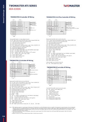
General Catalouge - 2024  40A-6300A                        TWOMASTER-S & S Plus Controller 4P Wiring


                TWOMASTER-B Controller 4P Wiring

                                                                        I Power                              II Power
                     I Power                              II Power
                  L1   L2    L3   N
                          L1   L2    L3   N
                                              Output 220VAC
                                                                                                Normal Power
                                              Normal Power
                                                                                                Normal Power ON
                                              Normal Power ON       L1   L2    L3   N  L1   L2    L3   N  Output 220VAC
                                              Output 220VAC                                     Output 220VAC
                                              Reserve Power                                     Reserve Power
                                              Reserve Power ON                                  Reserve Power ON
                                                                                                DC24V Aux. Power
                                     Controller                                        Controller  Fire Linkage for S controller /
                                             Fire Linkage
                                                                                                Current Transformer input for S Plus controller
                                             Generator Control                                  Generator Control
                                                                                      Display Controller
                  L1   L2    L3   N                                 L1   L2    L3   N
                   Load                                               Load
               Twomaster-B Controller terminal wiring instruction  Twomaster-S Controller terminal wiring instruction
               101-103 : Main Power external Indicator signal output ( Active AC230V 0.5A)  101-103 : Main Power external Indicator signal output ( Active AC230V 0.5A)
               101—Indicator common null line and 3P null line input  101—Indicator common null line and 3P null line input
               102—Main power indicator signal output             102—Main power indicator signal output
               103—Main power ON signal output                    103—Main power ON signal output
               201~203:Backup power external indicator signal (Active AC230V/0.5A)  201~203:Backup power external indicator signal (Active AC230V/0.5A)
               201—Indicator common null line and 3P null line input  201—Indicator common null line and 3P null line input
               202—Backup power indicator signal output           202—Backup power indicator signal output
               203—Backup power ON signal output                  203—Backup power ON signal output
               401~404  fire linkage control signal input and feedback signal output  301~302 aux. power DC24V input
               401,402-- Fire linkage signal passive input,       301--DC24V “+” input
               403,404–  Feedback signal when ATS transfer to OFF position      302– DC24V  “-” input
               501-503 : Generator start control signal output    401~404  fire linkage control signal input and feedback signal output
               501--Control signal NC point                       401,402-- Fire linkage signal passive input,
               502--Control signal common point                   403,404–  Feedback signal when ATS transfer to OFF position
               503--Control signal NO point                       501-503 : Generator start control signal output
                                                                  501--Control signal NC point
                                                                  502--Control signal common point
               TWOMASTER-E Controller 4P Wiring                   503--Control signal NO point
                    I Power                              II Power
                                                                  S Plus Controller terminal wiring instruction
                 L1   L2    L3   N  L1   L2    L3   N
                                                                  401~404  current signal input, 100mA
                                             Output 220VAC
                                             Normal Power
                                             Normal Power ON
                                             Output 220VAC
                                             Reserve Power
                                             Reserve Power ON      TWOMASTER-R Controller 4P Wiring
                                            DC24V Aux. Power
                                                                        I Power                              II Power
                                    Controller                       L1   L2    L3   N  L1   L2    L3   N
                                            Fire Linkage for S controller /
                                            Generator Control
                                   Display Controller  601  A +
                                         602  B -  RS 485 Communication interface
                                         603  GND
                                                                                                Common point
                                                                                        Controller  I Power ON Passive
                                                                                                0 position Passive
                 L1   L2    L3   N                                                              II Power ON Passive
                   Load
                                                                                                Common point
                                                                                                I Position output
                                                                                                II Position output
               Twomaster-E Controller terminal wiring instruction
               101-103 : Main Power external Indicator signal output ( Active AC230V 0.5A)
               101—Indicator common null line and 3P null line input
                                                                     L1   L2    L3   N
               102—Main power indicator signal output                 Load
               103—Main power ON signal output
               201~203:Backup power external indicator signal (Active AC230V/0.5A)
               201—Indicator common null line and 3P null line input  Twomaster-R Controller terminal wiring instruction
               202—Backup power indicator signal output           401~404  Remote control signal input
               203—Backup power ON signal output                  401-- Common point
               301~302 aux. power DC24V input                     402-- I Power ON passive input
               301--DC24V “+” input                               403-- 0 position passive input
                 302– DC24V  “-” input                            404-- II Power ON passive input
               401~404  fire linkage control signal input and feedback signal output  501-503 : Position signal output
               401,402-- Fire linkage signal passive input,       501--Common point
               403,404–  Feedback signal when ATS transfer to OFF position  502--I Position passive signal output
               501-503 : Generator start control signal output    503--II Position passive signal output
               501--Control signal NC point
               502--Control signal common point
               503--Control signal NO point
               601~603: RS485 Communication terminal  601--A+ , 602– B- , 603--GND
              Note: 1. If fire-fighting equipment output signal is active power, the signal source need to change over the line connection, for example to connect through a relay to change the
                   line connection,and connect the relay NO point to 401,402, when NO contact point closed ATS transfer to OFF position. When the fire linkage function is active, the ATS
                   will stop working,if want the ATS to working again, must first clear up the fire-fighting signal and then the ATS will recovery normal operation. If it is intelligent type , need
                   switching Manual/Auto button one time.
                  2. When the backup power is Auto start generator, when normal power is good 501 and 502 closed, 502 and 503 open; When Normal power is fault, 501 and 502
                   open, 502 and 503 closed.
                  3. RS485 Communication interface manual please refer to communication protocol.
    124